


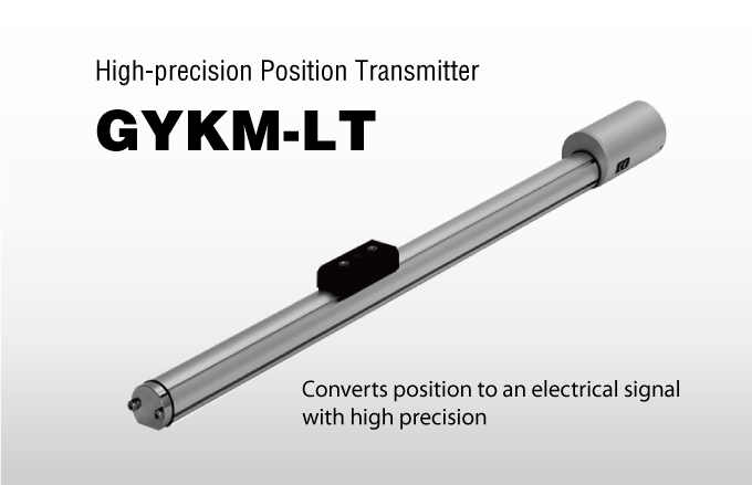
High-precision Position Transmitter GYKM-LT
Feature
There is no contact between the magnetostrictive wire and the slide magnet, so mechanical service life is maximized. Resolution not exceeding 0.01%, linearity not exceeding 0.025%
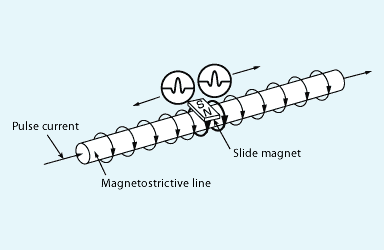
Operating principles
When a pulse signal flows in the magnetostrictive wire inside the transmitter of the high-precision position transmitter, a magnetic field is generated around the wire. Placing a magnet in this field causes mechanical vibration in the magnetostrictive wire, and the vibration propagates along the wires at the speed of ultrasound. The time of propagation is measured to gauge the position of the slide magnet.
Specifications
Model : GYKM-LT
Stroke : 350 mm
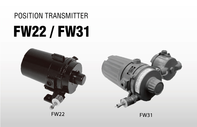
Analog Position Transmitter FW22, FW31
Overview
CONVERTS POSITION, GATE, WIDTH, WEIGHT etc. into ELECTRICAL SIGNALS.
Wire Position Sensor
The Analog Position Transmitter incorporates a precision potentiometer and converts the linear motion of an object to be measured into electric resistance proportional to its position.
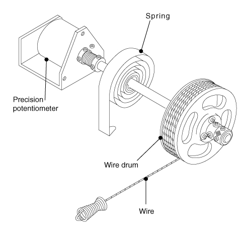
Structural Diagram
A stainless steel wire is wound around a wire drum which incorporates a spring. The shaft of the drum is connected to the shaft of the potentiometer.
Specifications
Output: 0 – 2000Ω
Overview
The Power Guide servo valve is back, lighter, and with even stronger erformance than ever before. Compatible with older models through a specialized adapter, and as easy to use as ever, Power Guide servo valves combine high performance and convenience with the toughness to work in dirty environments, changing the face of industrial servo valves.
Feature
Compact
Smaller and lighter, the unit has only one fifth the volume of previous models.
High responsivity
45Hz/-3dB
Power Guide servo valves feature high responsivity and high gain, with low hysteresis, achieving high levels of precision in EPC and CPC.Maintenance
The structure uses a double pilot format proven over extended use. The simple servo valve structure is even usable with general hydraulic oil*.
*: Hydraulic oil of NAS11 grade may be used, but there may be problems with NAS11 or lower if there is a high concentration of debris of 5μ or smaller.
Overview
The PILOTJET is an industrial servo valve for converting electric signals (-200 to +200 mA DC) Please confirm with client. Into hydraulic signals, which is used mainly for EPC® in steel plants. The PILOTJET uses a highly reliable jet pipe system that has been extensively used, to ensure high operability and easy maintenance.
Feature
- A dry detecting unit, that is not affected by magnetic dust in oil, reduces periodic maintenance.
- A jet pipe system with extensive experience of use provides hydraulic control.
- A servo mechanism for handing low to high flowrates is available in combination with a variety of gain boosters.
- A wide range of gain boosters is available with hydraulic pressures of 0.8 to 14 MPa.
- A simple structure allows for disassembly, reassembly, and adjustment in your plant.
- Easy operation and maintenance
Overview
High-performance EPC/CPC amplifier
The Strip Guide Amplifier is a high-performance, microprocessor-equipped EPC/CPC amplifier.
It offers advanced EPC/CPC controls such as stagger winding and cascading which are unavailable from conventional analog amplifiers. Also, this product is one-ninth the volume and one-fourth the weight of previous products. Finding the installation space is no longer an issue.
Feature
- The LCD screen makes it easy to check setting values and output signal status.
- All operations use the push buttons on the control panel for parameter settings.
- Control is possible by P, I or PI action.
- A line speed signal input enables automatic adjustment of control gain to compensate for changes in line speed. PLG signal input enables stagger winding.
- Sensor signals can be taken from up to two sensor systems, enabling cascading control operation.
OPTION : The SGA3000 stores control signals and output values in its ring buffer, which helps solve problems quicker.
Overview
The Photohead is the sensor of an EPC (Edge Position Control) system. It uses optical means to detect the edge of a strip (web).
The sensor signal is transmitted to an amplifier, and the amplified output signal is forwarded to a hydraulic jet pipe type controller or a servo valve, controlling the strip edge, so that it remains at the determined position.
If the operating environment of the Photohead is exposed to airborne dust, or if there is the risk that oil or water droplets etc. could fall onto the Photohead projector lens, use a sensor with the air purge specification.
Feature
The Photohead utilizes parallel light flux and detects the edge position of a strip (web) electrically.
Overview
The Autowide Sensor AWL is used mainly for CPC (center position control) to detect the center line on a strip (web).
It can continuously control the center line at a constant position without changing the position of the sensor each time the width of the strip changes (large changes such as seams etc.). The AWL is a new generation of detector which uses a highfrequency LED as the projector and SPDs(silicon photo diodes) as the detector.
Feature
- The LED of the light source ensures a longer service life.
- The SPD of the detecting element ensures a higher response than conventional sensors.
- The light source is lit at a high frequency and is synchronized.There is almost no effect from peripheral light(less than 1/50,compared with a fluorescent lamp-type Autowide Sensor).
- The sensor gap be fixed at any position.
Principle of Operation
The right and left detectors detect the deviation of the strip edges from the center line, and send signals the amplifier. The amplifier amplifies the difference between the right and left signals and sends the signal to the hydraulic controller or electric controller to perform CPC. When a strip travels with its center coincident to the center of the line, the signal from the amplifier is zero. In this state, the work cylinder is positioned at the center. When a strip deviates either to the right or to the left, the positive or negative signal, which is determined by the direction for correction, is transmitted to the controller, and the cylinder works in the direction to correct the displacement of the strip.
Overview
Continuous maintenance-free operation Next-generation CPC Sensor Using Electric Flux Lines
The Capacitance Autowide Sensor AWC is a sensor system that provides continuous, contactless detection of the center position of a strip moving on a line, for use in Center Position Control (CPC). Like our previous sensors, the sensor is maintenance free and can be used continuously with no decline in sensitivity caused by wear over time, giving stable, long-term service. The sensor is now a far easier product to use, offering improvements such as taking away the need for on-field calibration*.
* If there are metal structural elements close to the sensor, some simple adjustment may be required.
Feature
- No field calibration required
- Maintenance free
- Uninfluenced by light
- Insensitive to dirt, scale
- Unaffected by passline changes or wavy edges
Overview
New Concept— Detection by Electromagnetic Wave.
The furnace can operate safely because there is no need for sensors or other structures inside it.
Electromagnetic CPC sensors are new kind of sensor. They emit electromagnetic waves from antennae embedded in the furnace wall and use the transmission time taken for the waves reflected from the strip edges to return to the antennae to measure the strip position.
Feature
- The system operates safely because there is no interference with the strip and equipment inside the furnace.
- No maintenance is required.
- Dirt (dust and fumes) in the atmosphere inside the furnace has no effect. There are no consumable parts.
- The sensors are compact and light, for easy installation in a small space.
- Construction costs are low.
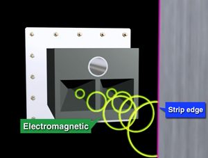
Detection operating principles and equipment configuration
Electromagnetic waves from the antennae are reflected from the strip edges and the transmission time taken for the waves to return is used to measure the strip position. Even if dirt or other contaminants reduce the reception sensitivity, the transmission speed of the waves does not change, so the measurement is unaffected.
Overview
Introducing strip position detectors with outstanding environmental resistance that use an electromagnetic induction method!
AWI Autowide Sensors are used in CPC (Center Position Control) to continuously detect the position of the center of strip without physical contact.
These sensors are maintenance free and can be used continuously. There is no loss of sensitivity due to component deterioration over time. Not only will they perform steadily for a long period of time; they do not require on-going on-site calibration, which makes them significantly easier to use.
Note: Simple calibration using a calibration jig is required for initial adjustment on site.
Feature
- On-going on-site calibration is not necessary
- Maintenance free » Different to optical sensors, AWI sensors do not require maintenance
- Unaffected by light » These sensors are hardly affected at all by external light
- Even under extreme environments » These sensors are hardly affected at all by dust or scale
Operating principles
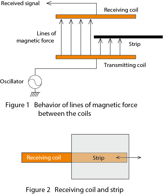
The AWI sensor generates lines of magnetic force between coils on either side of the strip and measures the changes in the position of the strip passing between the coils from the amount of change in these force lines (see Figure 1). The sensor has a transmitting coil and a receiving coil that are opposite each other, with the strip between them. The transmitting coil generates magnetic force lines and the receiving coil receives them. When a strip enters the gap between the transmitting and receiving coils, some of the magnetic force lines from the transmitting coil are blocked, which causes a variation in the magnetic force lines received by the receiving coil (see Figure 2).
Therefore, by calculating the amount of change in the lines of magnetic force received by the receiving coil, the position of the strip can be accurately detected
Overview
Wire Position Sensor
The FW80 analog position transmitter has two versions: a long-stroke type and an ultra-precision type. The position transmitter incorporates a precision potentiometer, and converts the linear motion of an object to be measured into electric resistance proportional to its position. A construction drawing of this device can be found in Fig. 8. A stainless steel wire is wound around a wire drum, which incorporates a spring. The shaft of the drum is connected to the shaft of the potentiometer via the synchro-belt pulley.
Structural diagram
A stainless steel wire is wound around a wire drum, which incorporates a spring. The shaft of the drum is connected to the shaft of the potentiometer via the synchro-belt pulley.
Specifications
Output0 to 2000Ω
Response speed
400mm/sec
Wire tension
45N (4.5kgf) max.
Ambient temperature-20°C to +80°C (standard)
Painted colorJIS7.5BG4/1.5
Weight8.6kg
Overview
This linear sensor is a one-dimensional image sensor applied to measure position with a high degree of accuracy
Feature
Simple Operation
・Operates using a single-voltage power supply (DC +15 V)
・Simply connect the power supply and a voltage (0 to 5 V) is output in proportion to the count (incident light pixel count).
・The count (incident light pixel count) is shown on the LED display, making it easy to check the operation.Wide range of scanning times
・The scanning time can be set from 2 msec to 20 msec.
Environmental resistance
・Can stably operate in an ambient temperature range of 0° C to +50°C.
Overview
The Modular Strip Guide system controller MGC1000 is an EPC/CPC controller that can be connected by communications cables to the other devices in the system to enable a flexible system configuration.
Feature
- The boards that comprise the controller are available as modules for each function. By connecting these modules via communications cables, you can configure the optimal system for your needs. This modular architecture enables boards to easily be changed in case of emergencies. It also allows the functions of the system to be easily upgraded as specifications change.
- The system can be externally commanded to switch between control of a maximum of EPC 1 to 8, CPC 1 to 4, Cascade EPC 1 to 4, Cascade CPC 1 to 2.
- The system can simultaneously actuate two hydraulic cylinders for CPC. (In-furnace CPC)
- Control via P, I, PI, PD or PID controllers is possible.
- The system can use either a nonlinear output in which deviations cause the output gain to change, or a speed gain output function in which the speed of the line changes the output gain.
- By inputting the PLG signal, the staggered roll function and tracking output function can be used. (Can be used in combination)
- The system can be externally commanded to shift the control position or the centering position. (The centering position cannot be changed (shifted) during cascade control.)
- The sleeve alignment function can be used. (It cannot be used during cascade control.)
- PROFIBUS and other Fieldbus interfaces are supported.
- Input/output locations for the interface signals, including the analog signals and the Fieldbus communication signals, can be set by parameter input.
- One controller can control up to four steerings.
- Data logging can be performed. (Optional)
Overview
The Photohead is the sensor in an EPC (Edge Position Control) system. It uses photoelectric principles to detect the edge of the strip (web). The sensor signal is transmitted to an amplifier. The amplified output signal is sent to a hydraulic jet pipe-type regulator or a servo valve and the strip edge is controlled so that it remains in the determined position. If the Photohead will be used in an environment where it will be exposed to dust, or if there is the risk that oil or water droplets could fall onto the Photohead projector lens, please use a sensor that has a guard or an air purge.
Specifications
Power supplySupplied from the LED dimmer unit (Power supply to the LED dimmer unit: DC 10 V 1 A (Max.)OutputA voltage (mV) in proportion to the change in light on the silicon light-detecting elementsSensitivityDetects a strip (non-transparent web) displacement of 0.1 mmAir purge air consumption400 Nℓ/min (at 0.05 MPa)Allowable back pressure within the case0.05MPaPaint colorSilverAmbient temperature-10 to +60℃Effective detection length20mmBody materialCast aluminum alloyLight sourceWhite LED 3 WMassPH50: 3 kgPH51 : See below
Overview
High-performance EPC/CPC amplifier
The Strip Guide Amplifier is a high-performance, microprocessor-equipped EPC/CPC amplifier.
It offers advanced EPC/CPC controls such as stagger winding and cascading which are unavailable from conventional analog amplifiers. Also, this product is one-ninth the volume and one-fourth the weight of previous products. Finding the installation space is no longer an issue.
Feature
- The LCD screen makes it easy to check setting values and output signal status.
- All operations use the push buttons on the control panel for parameter settings.
- Control is possible by P, I or PI action.
- A line speed signal input enables automatic adjustment of control gain to compensate for changes in line speed. PLG signal input enables stagger winding.
- Sensor signals can be taken from up to two sensor systems, enabling cascading control operation.
OPTION : The SGA3000 stores control signals and output values in its ring buffer, which helps solve problems quicker.